QCX-mini CW radio kit from QRP Labs
Hans G0UPL made yet another addition to the family of QCX transmitter kits. QCX+ is good as I wrote previously but QCX-mini is even better!
I was not lucky enough to get my hands on the kit from the very first batch but patience is gold. On a bright side revision 2 PCB I received does not require a hack with an additional capacitor in parallel with C38.
I’ve received the kit, built it and I love this tiny rig!
Same way as with my previous post I will try to avoid repeating the excellent build and operating manuals but I do have a few nits to pick.
Bonus: WSPR beacon mode test.
QCX+ was good but…
The first thing you notice of course is the smaller size of QCX-mini as compared to QCX+.
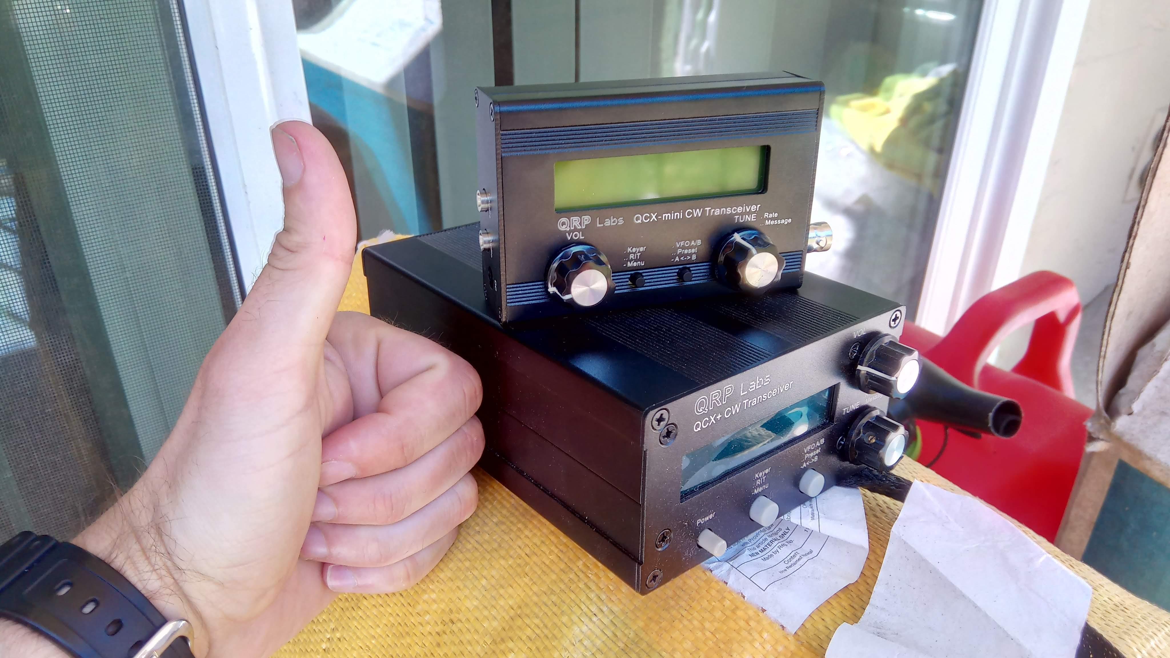
QCX-mini assembled as compared to QCX+
I like SOTA so rig size and weight matters quite a bit to me. QCX+ was acceptable but when it was laying flat it was quite hard to read the display. Also I really liked the fact that all controls and protrusions are on the “face” and “back” of the radio and unlikely to be peeled off in a backpack. QCX-mini is so tiny it does not matter where controls are - it will be safe in a padded accessory bag. The downside of course is less surface for heat dissipation - I plan to use the rig as a WSPR beacon and it will be keyed for about two minutes continiously. We’ll see how it holds, so far so good.
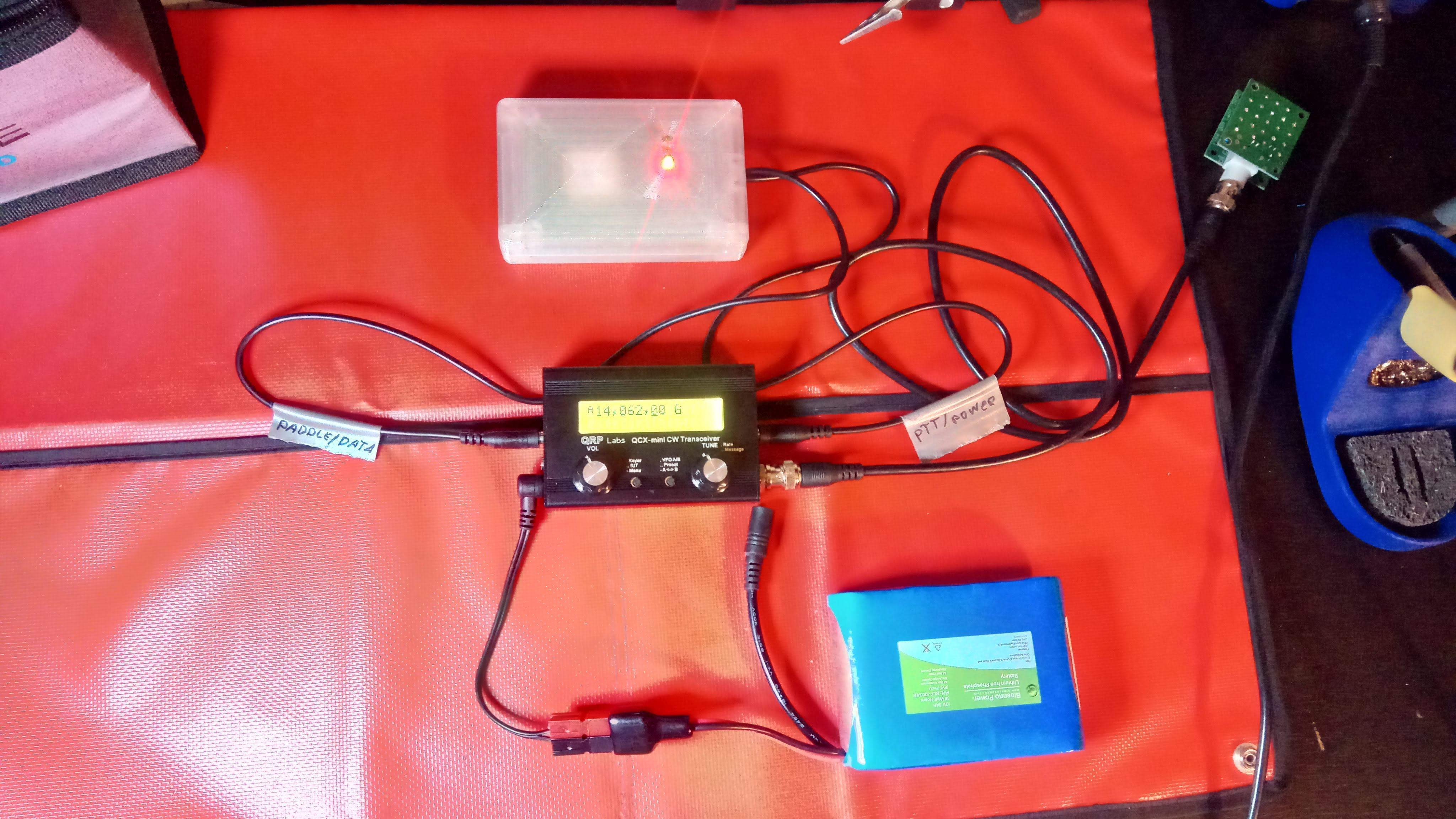
I really like the fact that PTT has +5 volt tip layout by default. I had to make the modification for QCX+ so I could use normal audio cable to key amplifier kit and also built GPS kit so it takes +5 volt from the tip. My GPS kit and amplifier are now naturally compatible with QCX-mini.
As it’s older brother QCX-mini puts out 3 watts with 12 volt battery (draws about 0.3 A on a key down), and about 15 watts with amplifier and 12 volt battery (draws about 3.2 A on a key down). Stand by current draw is about 0.1 A.
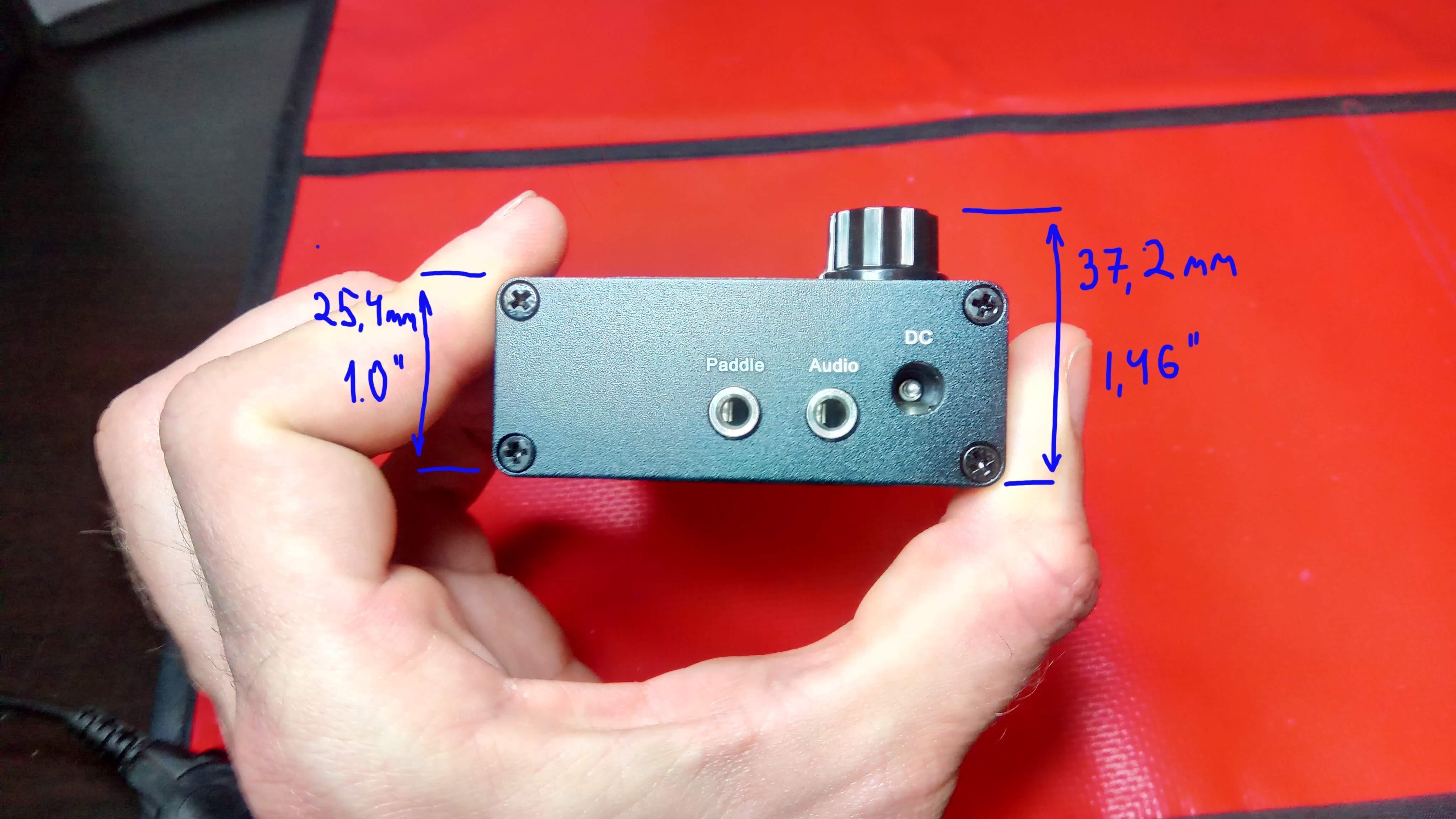
Dimensions and weight
Assembled transceiver weighs 200 g / 0.44 lb.
Front view and dimensions Side view and dimensions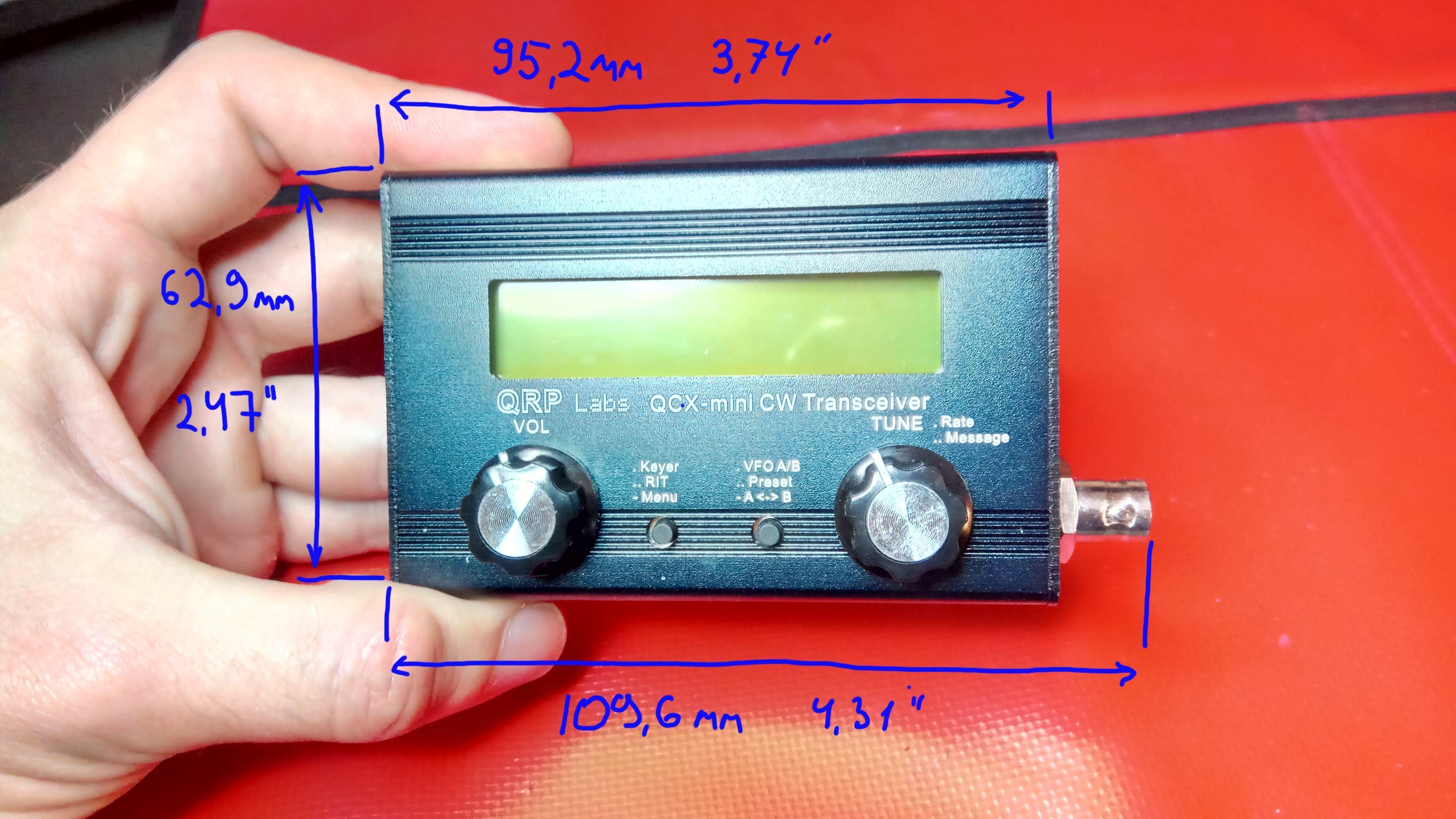
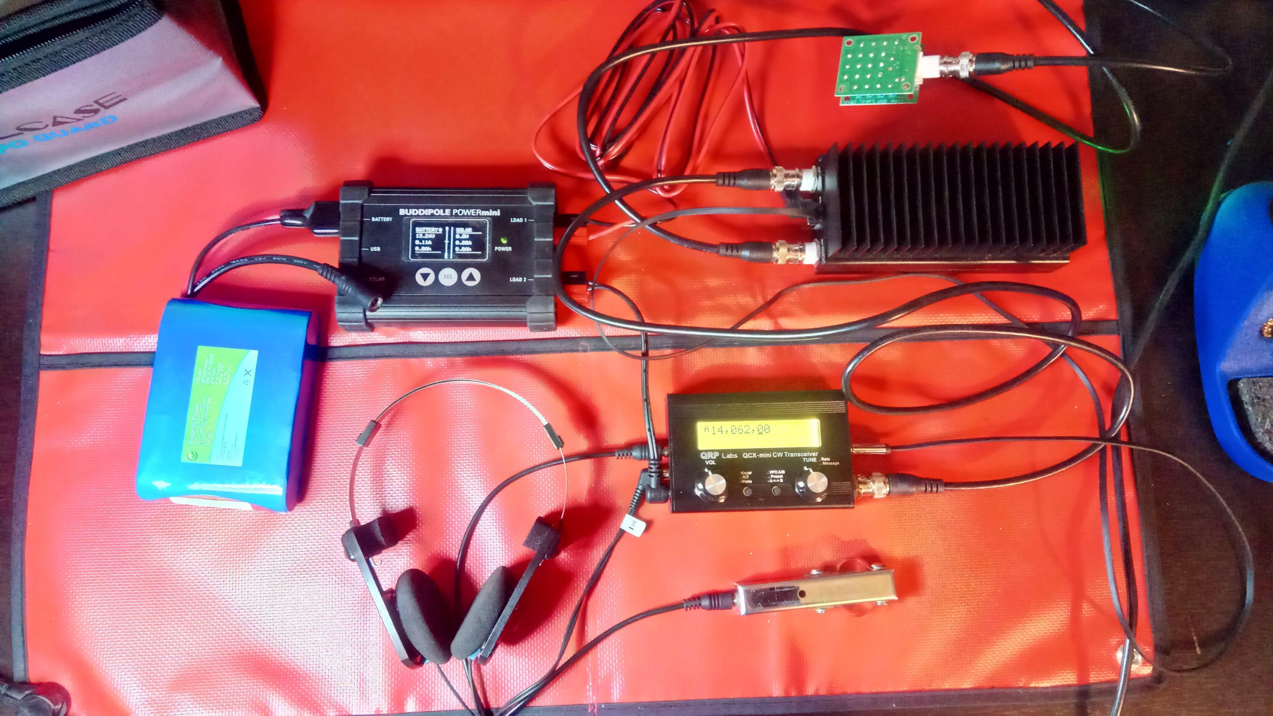
Modular system
What I like the most about the QCX system is its modularity.
Full system weighs about 4250 g / or 9.37 lbs. This includes
- QCX-mini (200 g)
- two batteries (2x394 g). One battery is spare, you may as well ditch the battery controller if you have two batteries
- Battery controller (181 g) to power both the transceiver and amplifier from one battery and optionally connect a solar panel
- Amplifier (382 g)
- Mast (700 g)
- Dipole antenna and pegs + emergency end fed just in case (654 g)
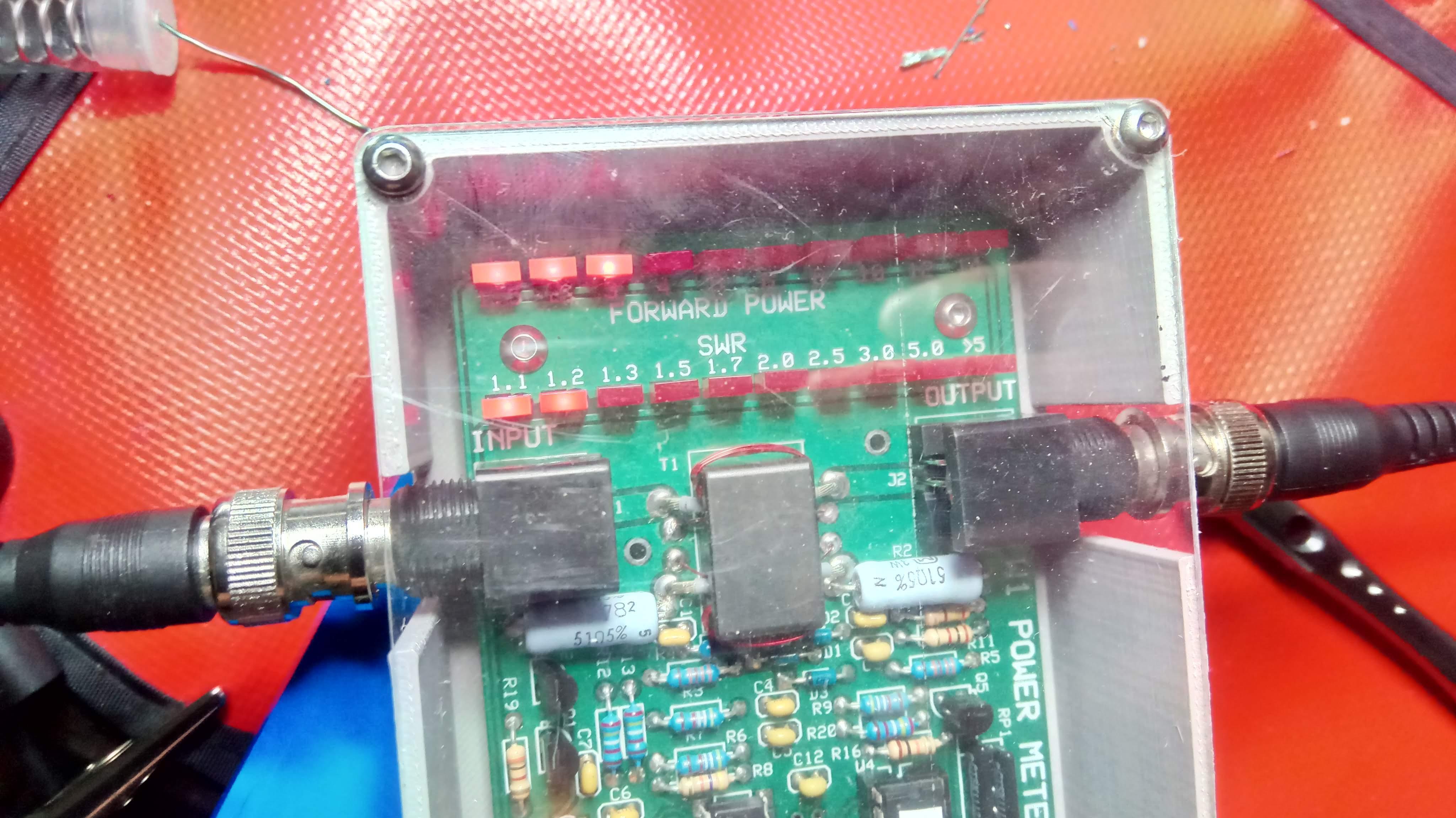
- Antenna tuner - in case you need to match an end fed antenna
- Phones, cables, titbits and doodads
With 12V battery standby current is 0.1 A, key down current 3.2 A, output around 15 W.
Full system packed. Collapsed mast length is 56 cm / 22 '' - for reference Full system assembled (no antenna)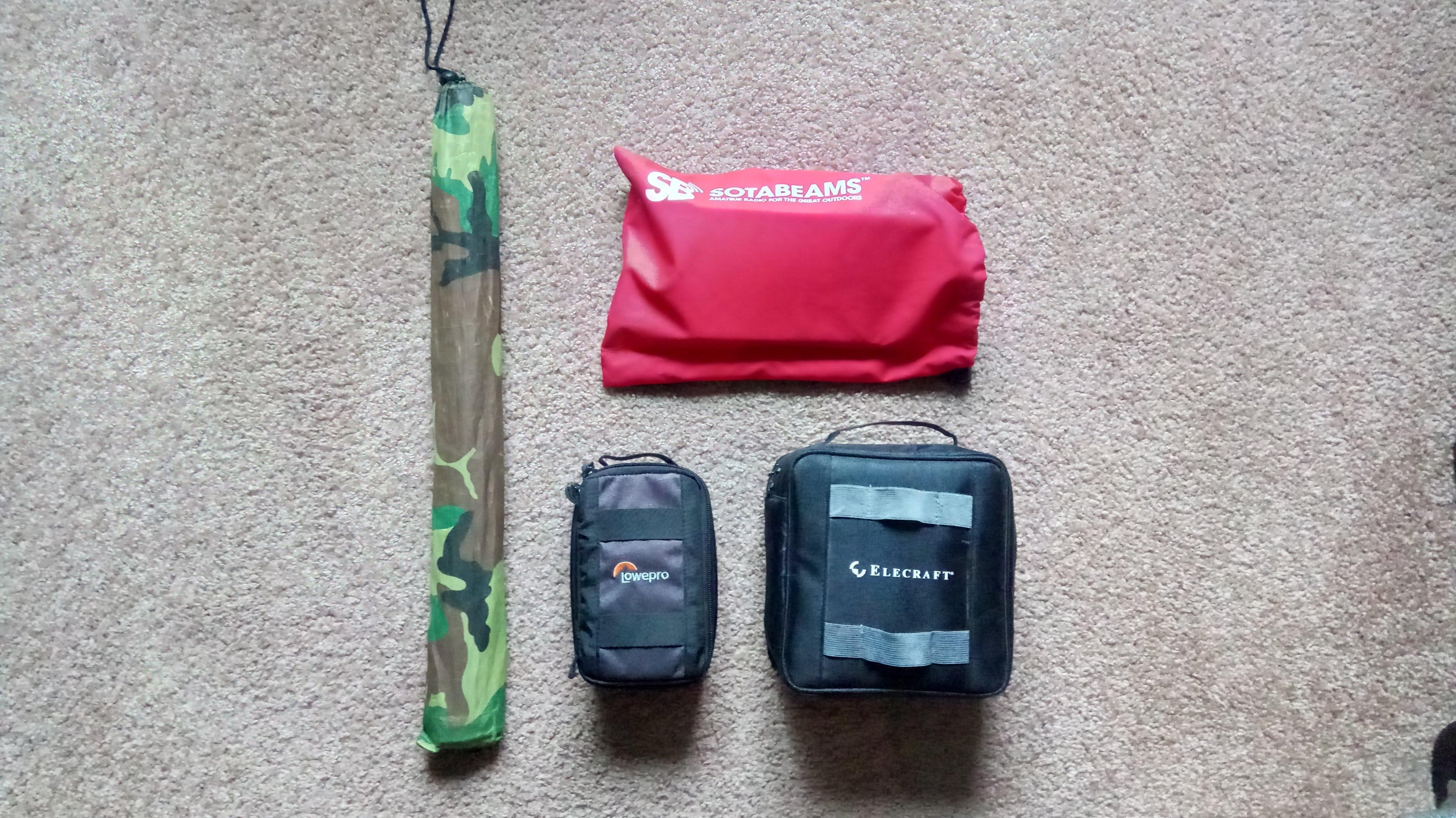
It is possible you don’t need 15 W and ok with just 3 W. You can ditch the amplifier, one battery, battery controller and some cables. With 12V battery standby current is 0.1 A, key down current 0.3 A.
Minimal setup, around 3 kg with antenna and mast 3 watts out with 12 volt battery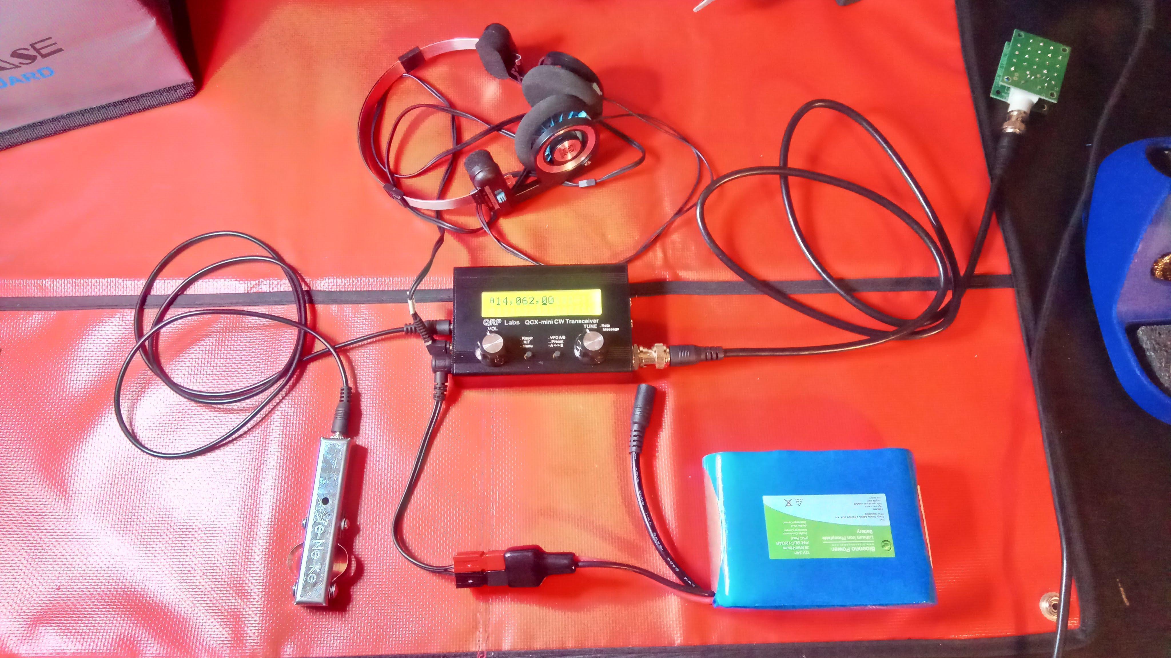
You can add a GPS kit and run QCX-mini as a WSPR beacon. In the photo below is an older version of GPS module in a 3d printed enclosure.
WSPR beacon with GPS module
Kit assembly tips
The main board is quite crowded now. While Hans boasts he assembled the kit using 3mm chisel iron without any issues I strongly recommend getting a decent iron or a soldering station. There are many pre-installed SMD components on the board and if you fry or move them with a bad iron you will probably need to wait another six month for a replacement kit.
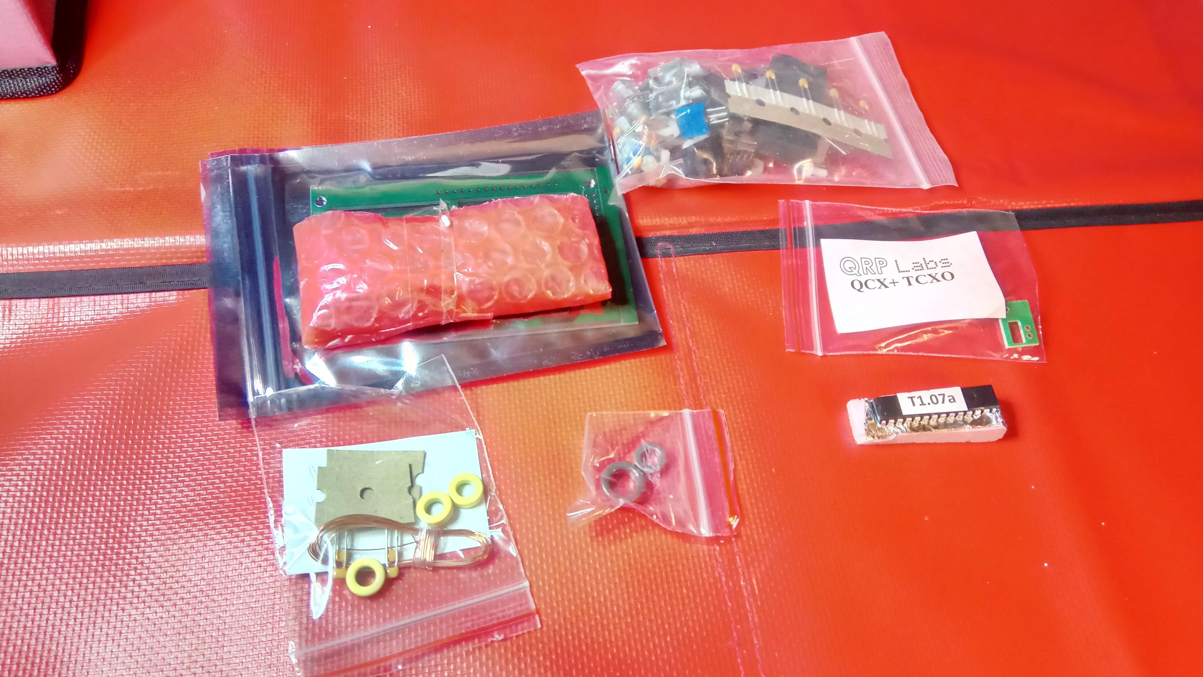
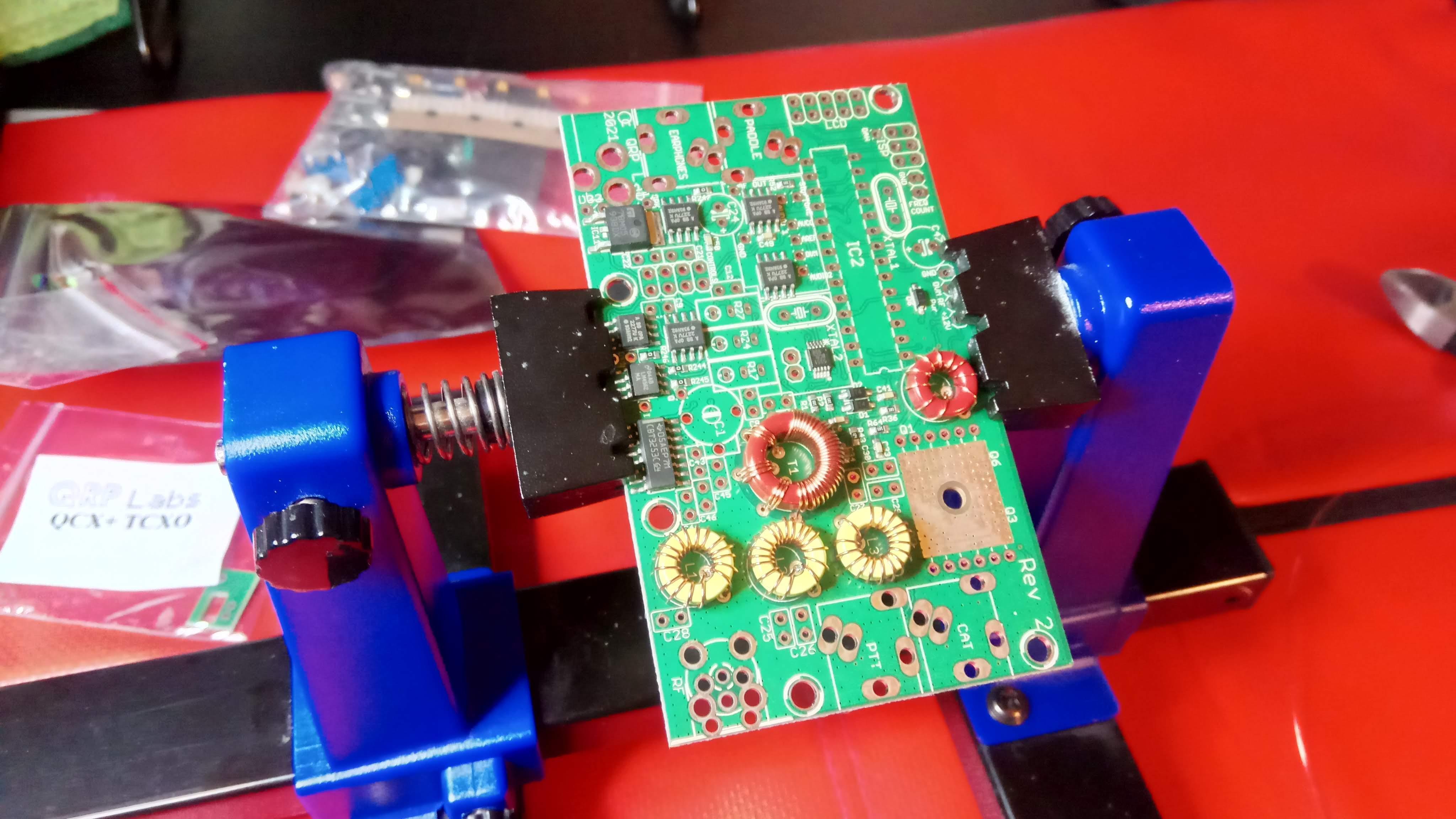
The kit with TCXO option
Do not throw away cut component legs - you’ll need a lot of them to connect the display, gain control potentiometer and rotary encoder later in the build.
You will definitely need a file or a dremel tool - you break control and display PCBs apart and need to file down the resulting jagged edges. It is critical if you plan to install an enclosure - control PCB needs to squeeze through a cut out in the display PCB and it just won’t without filing.
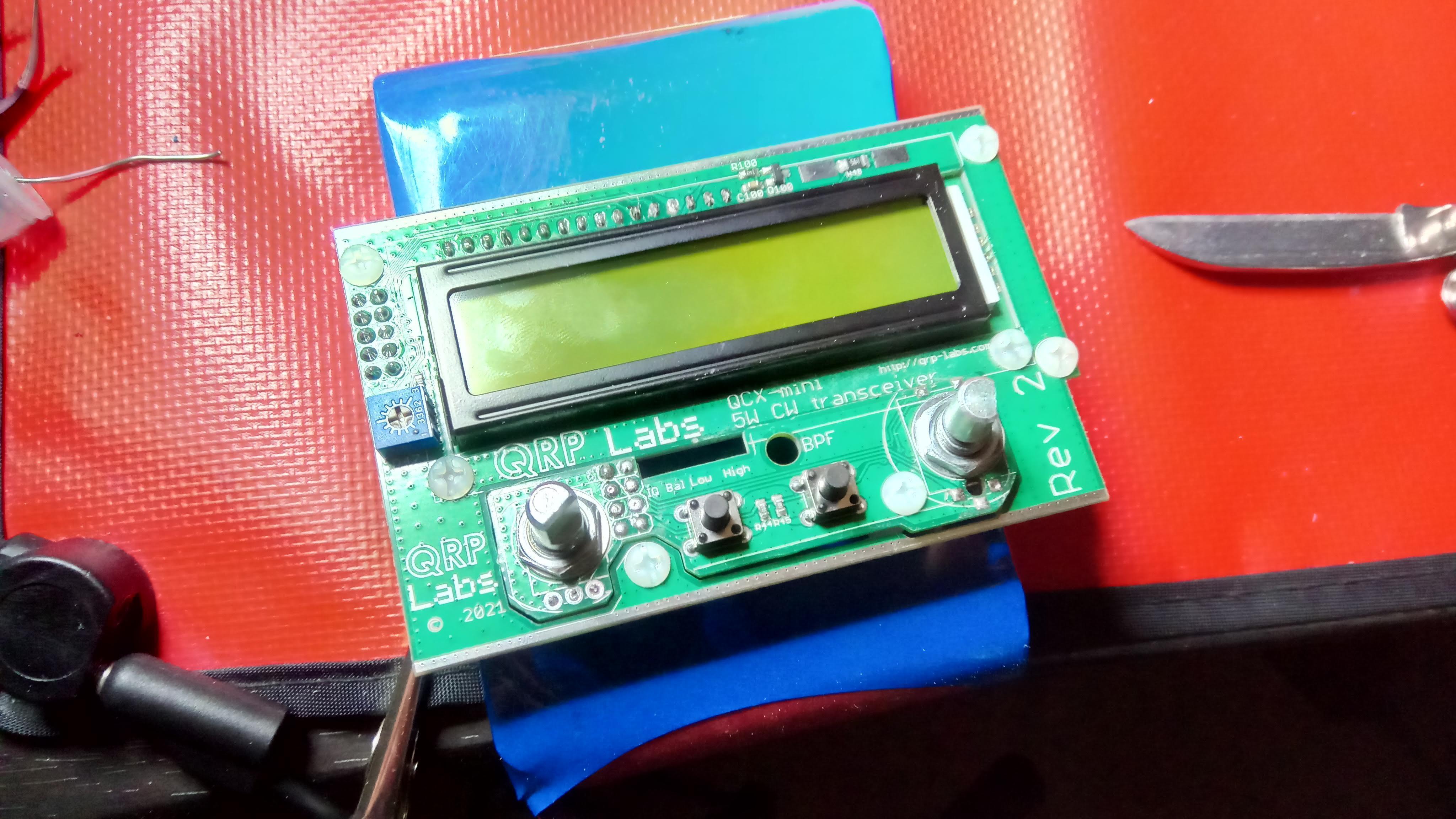
Make sure control board squeezes through the hole in the display board
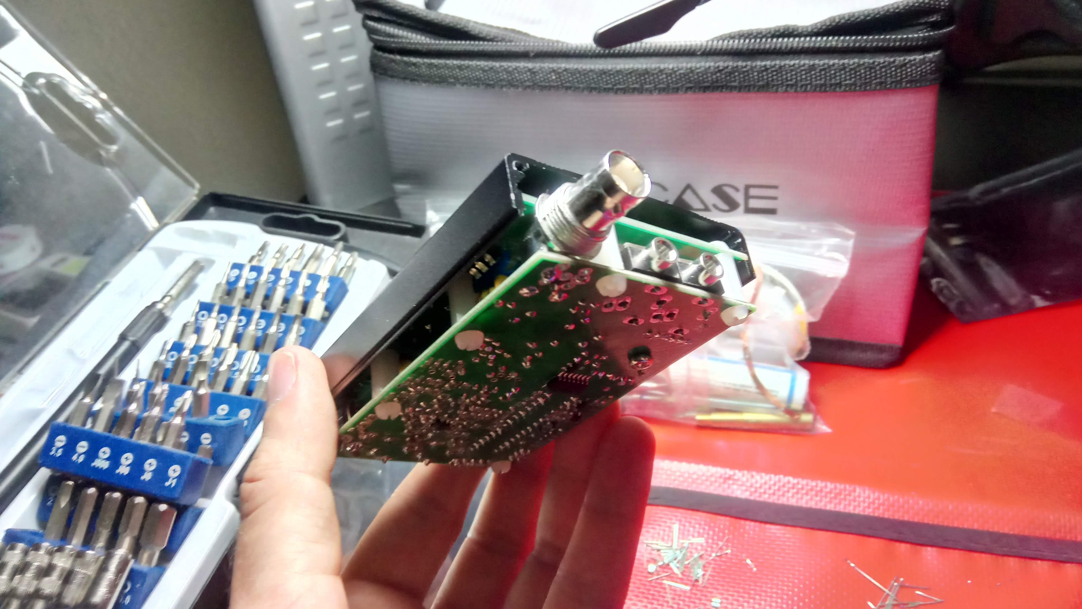
If you plan on installing an enclosure be careful when soldering the BNC connector. Best way to do this is to insert PTT and Cat 3.5mm jacks into the board first - they fit tight and won’t fall off. Then you insert the BNC connector and screw the enclosure side panel on it. Once you have these in place proceed and solder BNC connector and jacks. There is little room for error and no “play” in components - you want to make sure the enclosure side panel is exactly where it should be in respect to protruding components. Same goes for Paddle / Phones / DC jacks and other side panel - assemble before soldering and make sure everything is positioned correctly.
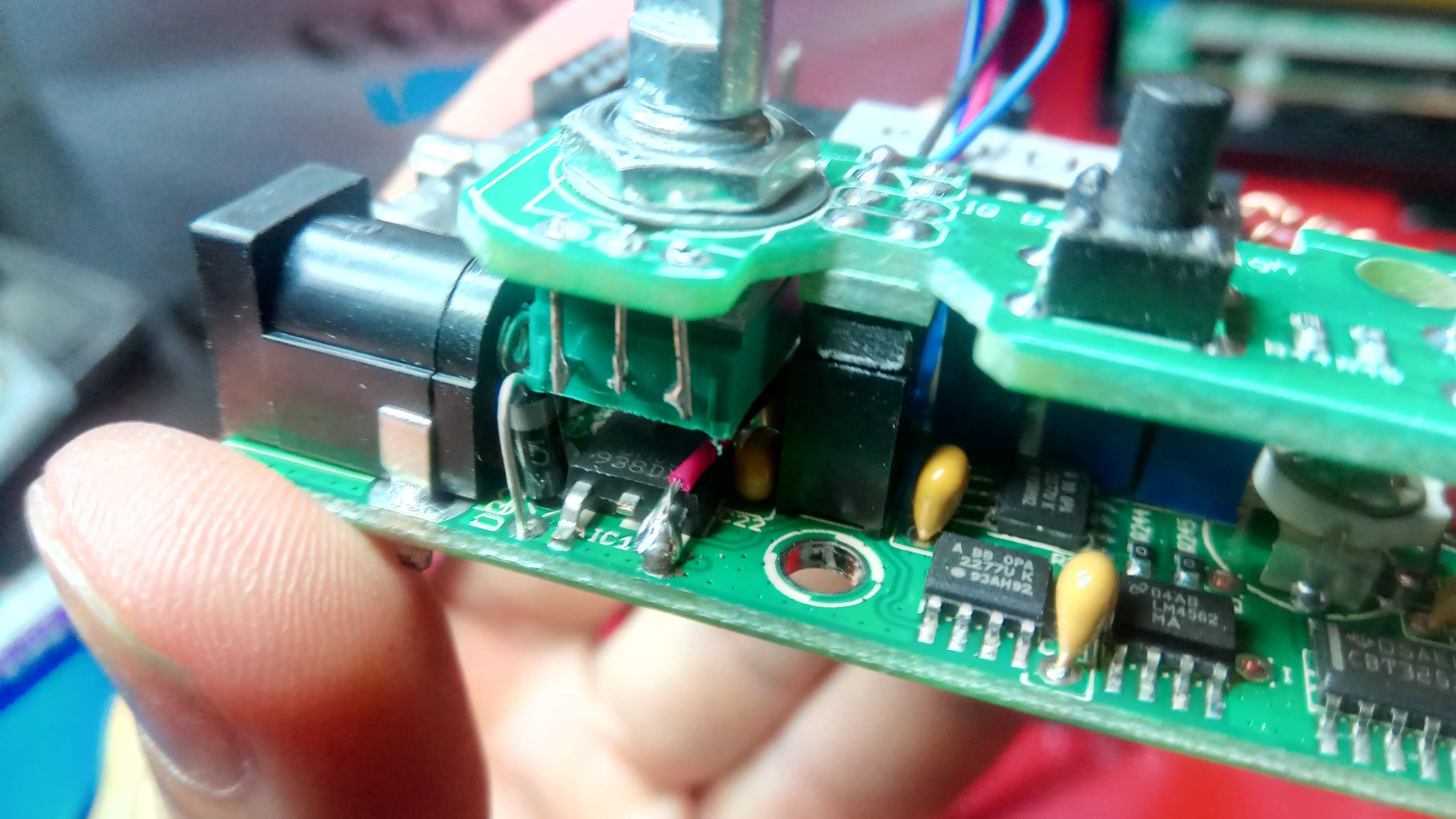
Be careful installing D33 diode - it is installed vertically and should sit as close to PCB as possible. 1.05 version of assembly manual has it positioned differently so feel free to check the photo below. Note how close it is to the DC jack. In the assembled rig it needs to fit under gain control potentiometer and if you’re sloppy here it won’t.
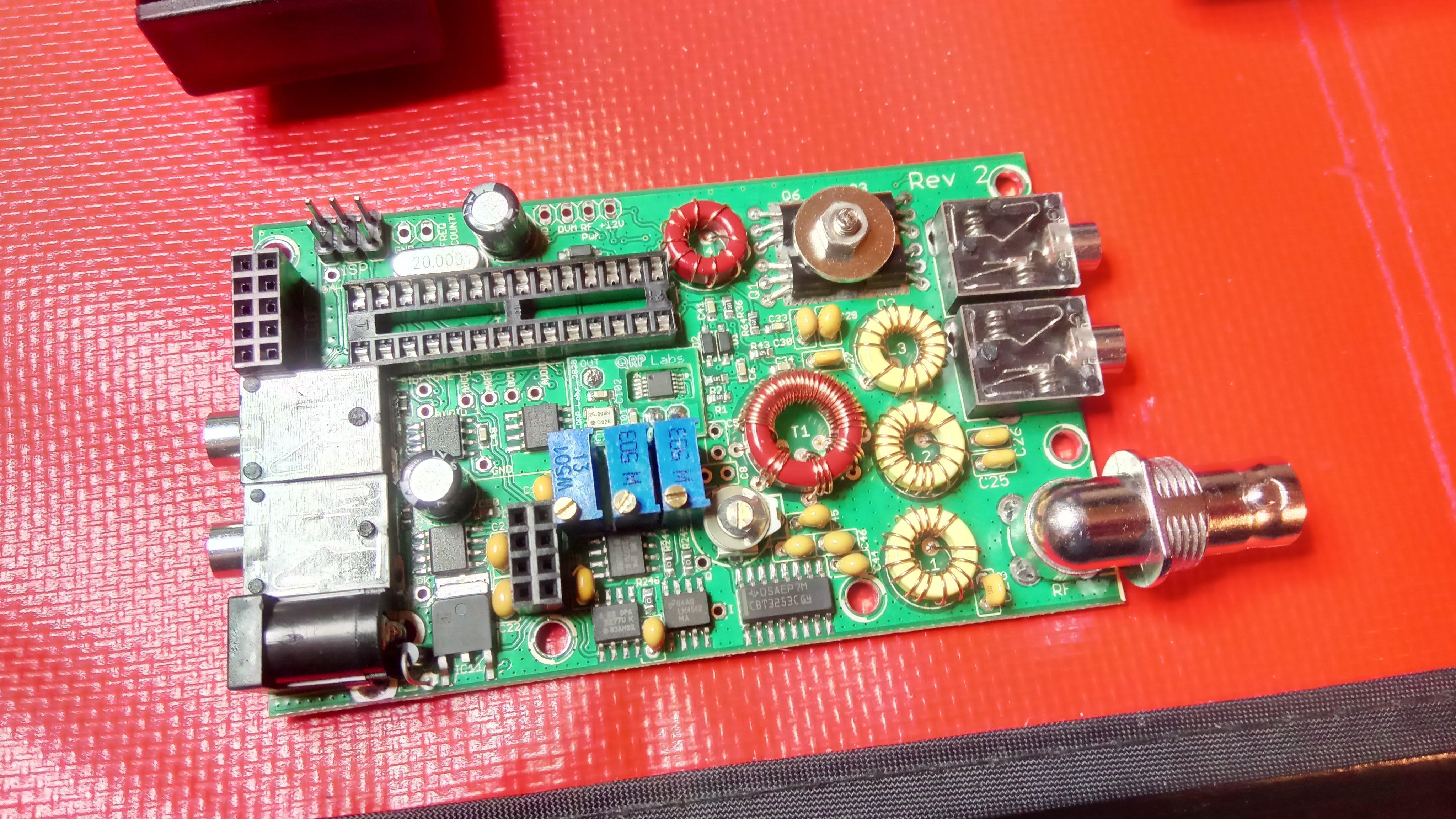
Quite a tight build note D33 diode near DC jack
My personal preference is to wind and install all coils first. This way is easier to test if they are soldered properly with a multimeter. Plus you don’t heat as many components up waiting for shellac to burn off the wire. The wire is very thin and shellac burns right away - no scraping required. Just test and if you hear no beep from multimeter heat again for a couple of seconds - should be enough.
Wound and installed coils first
And finally - just follow the instructions. The assembly manual is excellent.
Final touches before installing bottom part of the enclosure
Auto Gain Control add-on kit
One issue I’ve noticed operating QCX family rigs is that there is no built in AGC so volume of incoming signals varies significantly depending on how strong the signal reaching the antenna is. Quite often I’m cranking volume up trying to copy a station couple hops away and then some nearby station blasts in super loud. Yikes!
There is a small add-on Auto Gain Control kit available from Electron Volt (r) Shop that I believe helps a bit. I’m not sure about the kit availability in the future - when I bought mine in May 2020 there were only two more available but the page promised another batch.
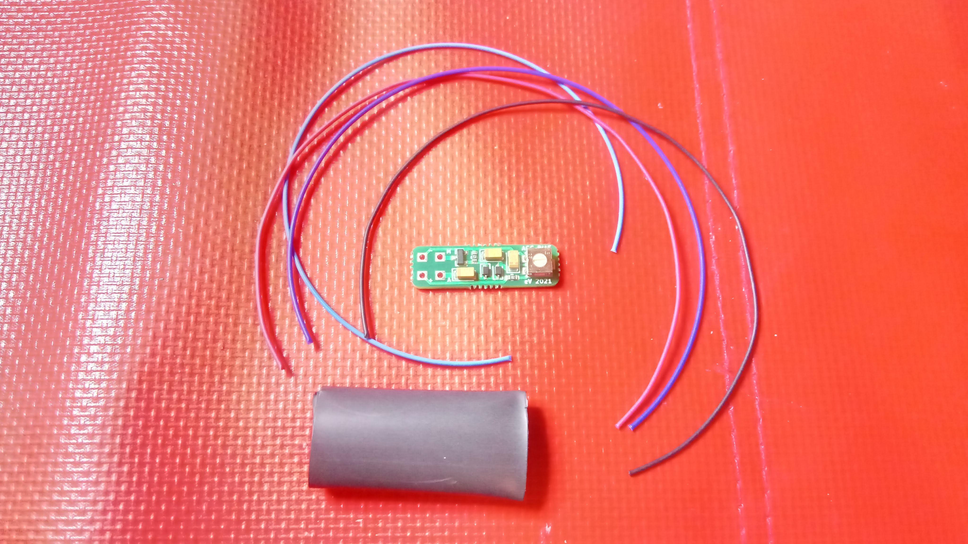
AGC kit prior to soldering
Wiring / assembly instructions are clear and easy to follow. Note photo for step 12 – ‘Prepare and solder the 5V wire’ in the manual is not correct. Contacts of voltage regulator IC11 from left to right are input voltage, ground and output voltage (+5V). You need to solder red wire to the rightmost contact, check the photo below. If in doubt - check with a voltage meter!
QCX-mini rev. 2, note red +5V wire soldered to the rightmost contact of IC11
Note the AGC is not too fast, does not bounce back completely between symbols sent so if you swear by full QSK operation this mod may not be ideal for you. Works just fine for me though.
Bonus: WSPR test
I actually didn’t have much luck using QCX+ as a WSPR beacon. Operation manual recommends enabling practice mode when connecting GPS module to prevent GPS module from keying the transmitter and frying PA. So I was duly enabling practice mode, enabling beacon mode and… nothing was happening really, no one heard me.
What the manual does not tell is that in practice mode no WSPR signal is being emitted as well. So yes, you just plug GPS module data into the paddle jack, enable WSPR beacon mode and let the radio decide what to do next.
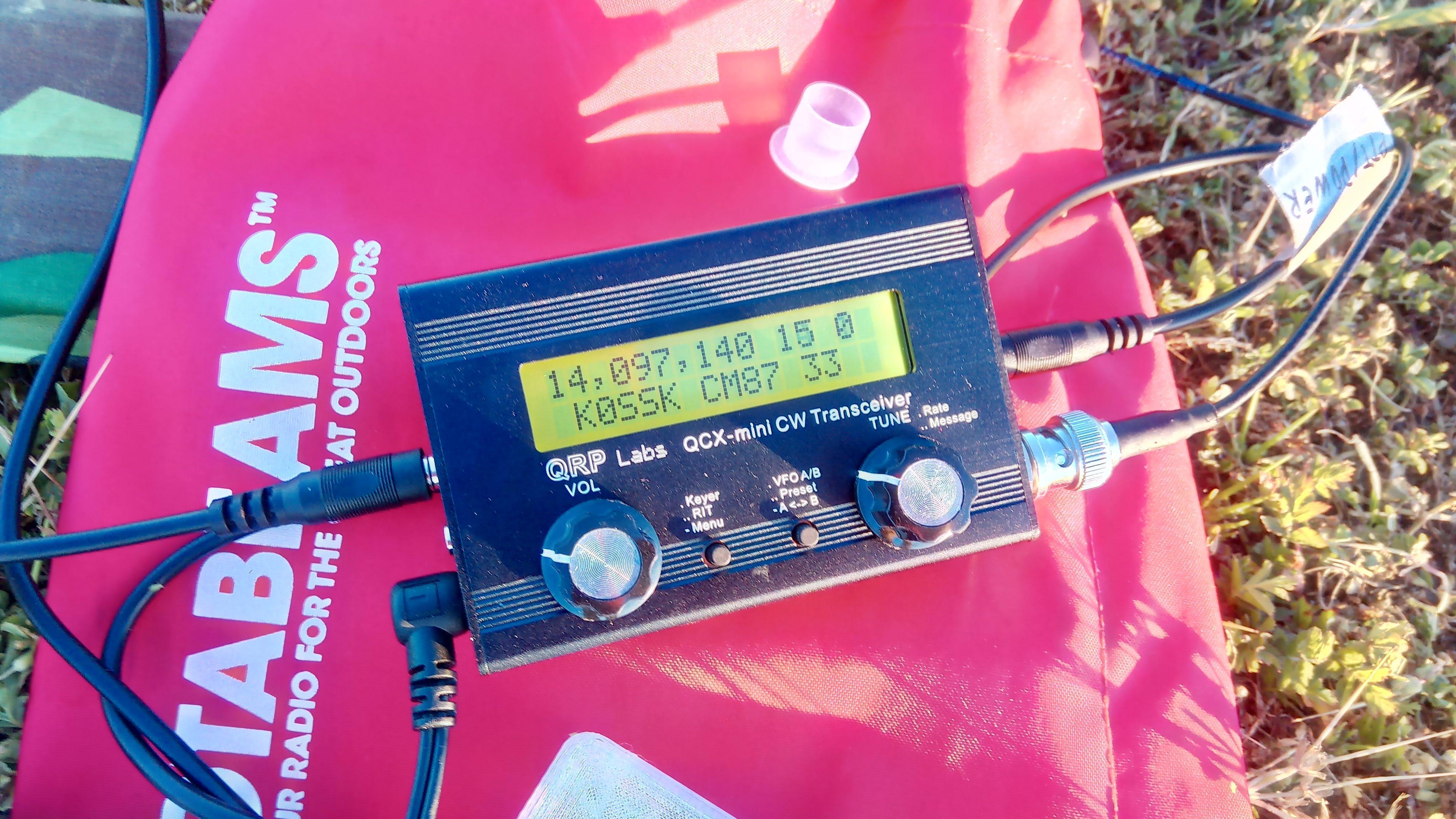
WSPR settings that worked for me:
- Mode: WSPR
- Frequency: 14,097,140 - default for 20 meter band.
- Frame: 06 - transmit every 6 minutes. I only work mobile so I don’t think this is to often and should be enough time for transistors to cool down
- Start: 06
- WSPR call: _K0SSK - this should be YOUR call sign just in case.
- WSPR power: 33 - about 3W.
- WSPR time and locator are configured by GPS module
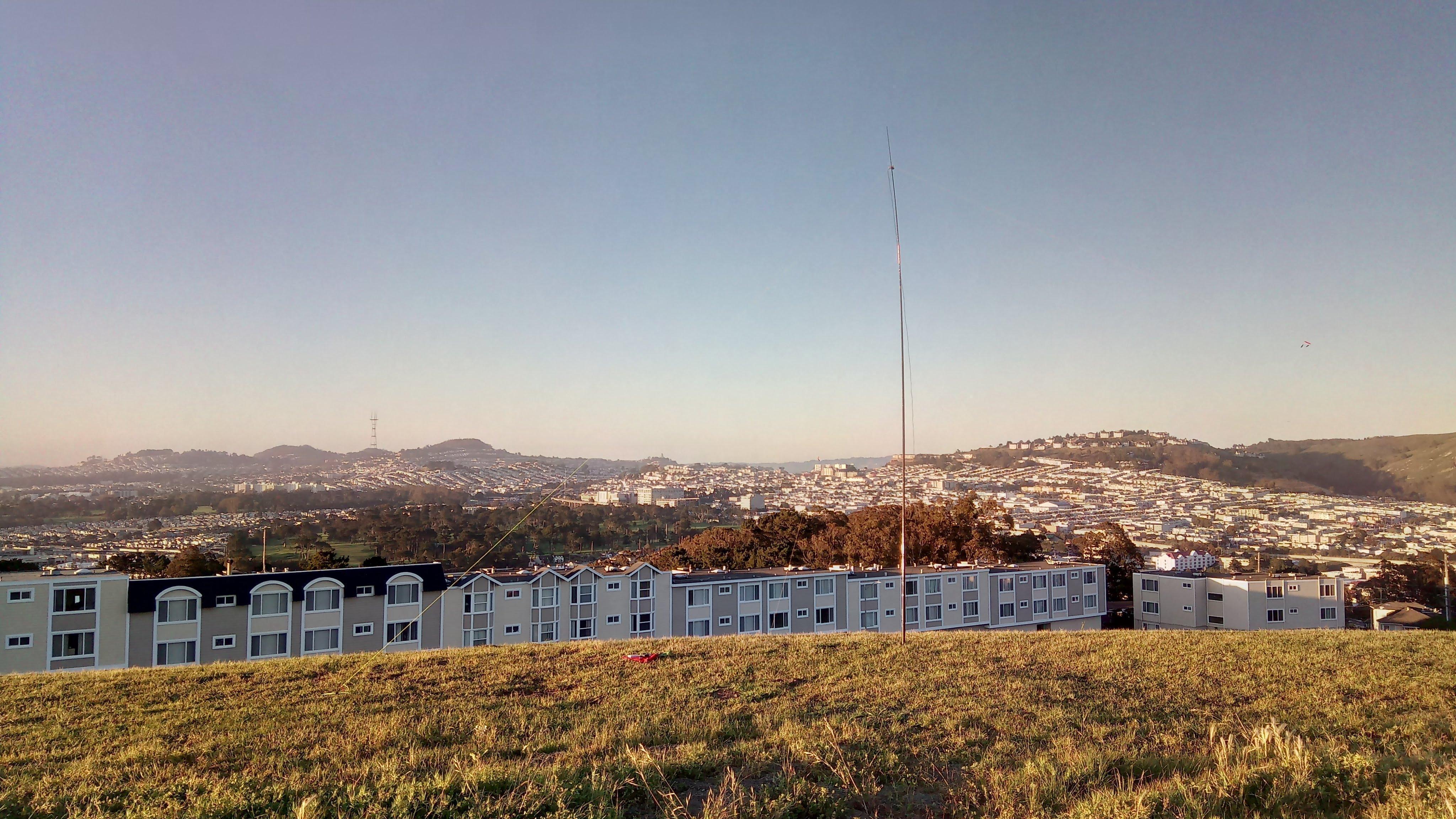
My humble dipole and Twin Peaks with Sutro Tower in the background - testing WSPR mode
And - voila! It works! Nice propagation reported for a 20 meter band at sunset. I wish I had as many SOTA contacts :)
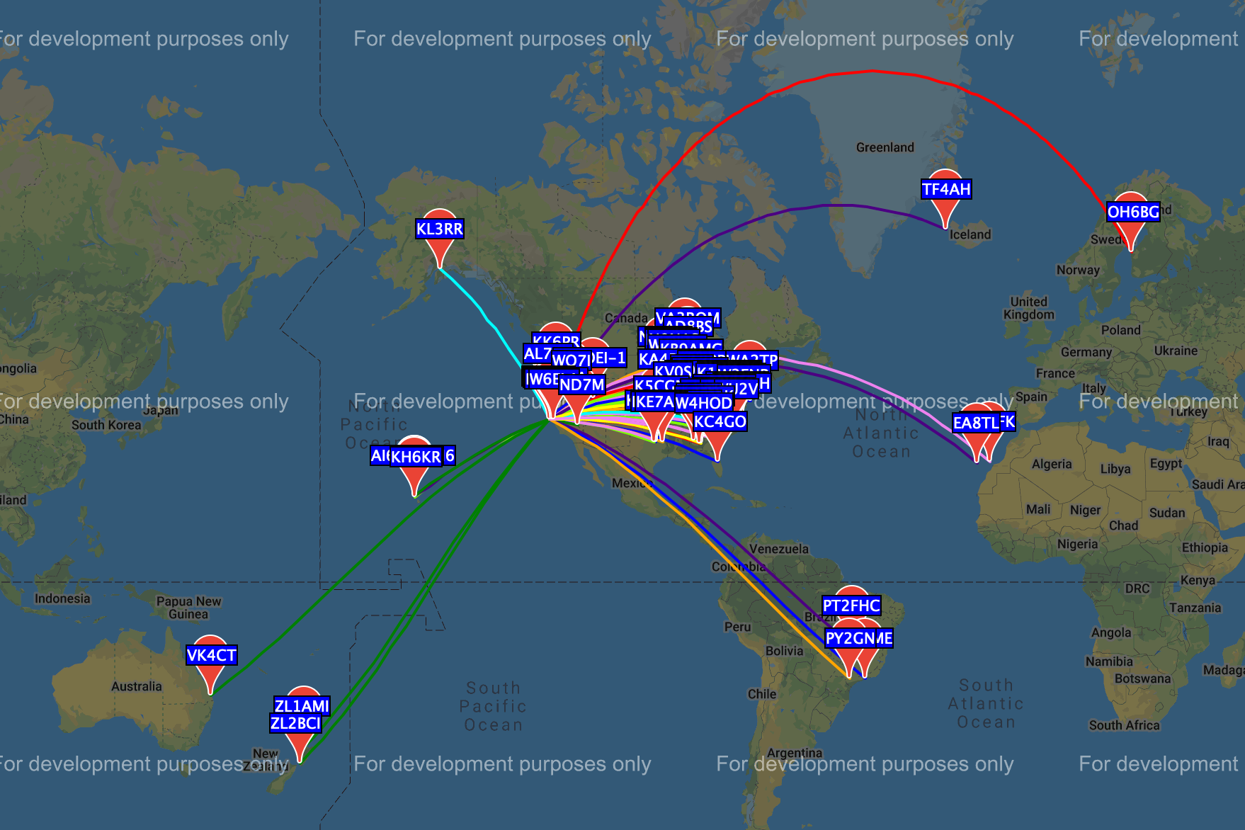
WSPR spots
See you next time, 73 K0SSK out!